
2018/2019 Physics Questions And Answers
Below are Physics Questions and Answers for WAEC
Alternative A
Question 1
(a) Diagram
You are provided with three retort stands, a pendulum bob, drawing board, stop-watch and other
necessary apparatus. Using the diagram above as a guide, carry out the following instructions:
(i) Fix the drawing paper on the drawing board and hold the board with two clamps such that
its vertical.
(ii)Suspend the pendulum bob such that it hangs freely in front of the drawing appear.
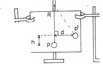
(iii) Draw a line RP representing the rest position of the pendulum string and mark the
position P of the centre of the pendulum bob at rest.
(iv) Displace the pendulum bob to one side in a plan parallel to the drawing board.
(v) Mark the new position p1 of the centre of the bob
(vi) Measure and record the perpendicular distance, d of pi from the line RP.
(vii) Evaluate and record d2•
(viii) Measure and record the vertical height h of p1 above P.
(ix) Evaluate G =d2/h
(x) Repeat the procedure for four other oppositions of p1
(xi)tabulate your readings
(xii) remove the drawing board so that the pendulum bob can swing freely.
(xiii) Set the pendulum bob oscillating through a small amplitude and determine the time t for
20 oscillations
(xiv) determine and record the period T.
(xv) plot a graph with G on the vertical axis and h on the horizontal axis, starting both axes
from the origin (0, 0).
(xvi) Determine the intercept 1 on the horizontal axis.
(xvii) Evaluate A = 1/(19.7)2
(xviii) State two precautions taken to obtain accurate results
(Attach your drawing paper to your answer booklet).
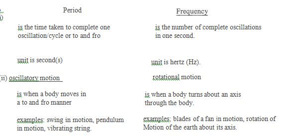
(b) (i)Distinguish between the period and frequency of oscillation of a simple pendulum.
(ii) Differentiate between oscillatory and rotational motions.
Observation: This was fairly popular question with many candidates. However, most candidates did not perform well. Majority of the candidates did joint work; those that did not, could not complete traces or did the traces poorly. Some did not even attach their traces. Some of the candidates with traces finds if difficult to measure the distance d and height, h.
The evaluation of A = (1)/19.7T2 was a problem to few candidates.
Part (b)(i) was well answered by most of the responding candidates.
Part (b )(ii). Some candidates defined circular motion instead of the rotational motion demanded by
the question.
You are provided with three retort stands, a pendulum bob, drawing board, stop-watch and other
necessary apparatus. Using the diagram above as a guide, carry out the following instructions:
The expected answers are:
Second observations: (i) Five complete traces showing positions of P and pi (deduct 1/2 mark for each missing position of P1)
Score zero if P is not shown.
(ii) Five values of d correctly determined and recorded in em to at least 1 decimal place.
(iii) Five values of d2 correctly evaluated to at least 3 significant figures
(iv) Five values of h correctly determined and recorded in em to at 1 decimal Place and in trend. (Trend: As d increases h increases)
(v) Five values of G correctly evaluated to at least 3 significant figures.
(vi) Value oft for 20 oscillations correctly determined and recorded in seconds to at least 1 decimal place.
(vii) Value of T correctly determined and recorded in seconds to at least 2 decimal places.
(vii) Composite table showing at least d, d2, hand G.
Note: 1. l fno traces attached, award zero for (i) - (iv).
II. 1ft is recorded more than once, accept the first value only.
GRAPH [06]
(i) Both axes correctly distinguished ~ mark each
(ii)Reasonable scales ~ mark each
(iii) Five points correctly plotted
(iV)Line of best fit
Note:If origin not shown, deduct 1 mark for d.i.
INTERCEPT (01)
Intercept I on the horizontal axis
correctly shown
correct read
EVALUATION (01)
Correct substitution of A = 1/19.7T2
Correct arithmetic
PRECAUTIONS [02]
Award 1 mark each for any 2 correct precautions:
e.g
Conical oscillation avoided,
Draught avoided during oscillation
Parallax error avoided when reading the metre rule/stop watch
Zero error noted and corrected for on the stop watch/rule.
Neat traces.
(Accept any other valid precautions).
(b)(i)
Alternative A
Question 2
(a) Diagram
You are provided with a glass block, plane mirror and optical pins.
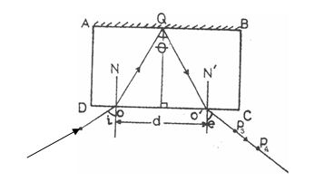
(i)Place the glass block on a drawing sheet and trace its outline ABCD as shown in the diagram above.
(ii)Remove the block, measure and record the width W of the block.
(iii)Draw a normal ON to DC at a point about one-quarter the length of DC.
(iv)Draw a line making an angle I = 10° with the normal
(v)Replace the block on its outline and mount the plane mirror vertically behind the block such that it makes good contact with the face AB.
(vi)Stick two pins PI and P2 on the line MO.
(vii) Looking through the face CD, stick two other pins P3 and P4 such that they appear to be in a straight line with the images of pins PI and P2 seen through the block.
(viii) Join P3 and P4 with straight lien and extend it to touch the face CD at 01•
(ix)Draw a perpendicular line from the midpoint of 001 to meet AB at Q.
(x)Draw lines OQ, OlQ and normal 01N1 produced.
(xi)Measure and record, e and d.
(xii) Evaluate m = sin e and n = cos [~]-
(xiii) Repeat the procedure for I = 20°, 30°' 40° and 50°.
(xiv) Tabulate your readings
(xv) Plot a graph with m on the vertical axis and n on the horizontal axis.
(xvi) Determine the slope, s, of the graph and evaluate q = 2Ws.
(xvii) State two precautions taken to ensure accurate results
(Attach your traces to your answer booklet.)
Observation: (a)This question seem to be popular among the candidates, however, it was poorly attempted. Some candidates just copied the diagrams as they appeared on the question paper without
actually performing the experiment. Some did not attach their traces while some traces do
not have the required pin holes.
(b) Part (b )(i) was poorly attempted. Though refractive index was well explained but expressing
it in terms of wavelengths was a mirage.
Part (b)(ii) was well attempted by majority of the responding candidates.
The expected answers are:
Observation
(i) The width W of the glass block measured and recorded in em to at least 1 decimal place.
(ii) 5 complete traces attached, showing at least incident and emergent rays, the normals ON and 01 N1 , and the rays OQ and Q01 as illustrated in the diagram.
(iii) 5 values of the emergent angles e measured and recorded in Degrees.
(iv) 5 values of angle 6 measured and recorded in degrees
(v) 5 values of d measured and recorded in em to at least 1 decimal place
(vi)5 values of m = sine e) correctly evaluated to at least 3 decimal places
(vii) 5 values of n = cos(θ/2)correctly evaluated to at least 3 decimal places
(viii) Composite table showing i, θ, e, m and n
Note: I. if traces are bit attached, award zero for (i) - (v)
II. if traces are attached but no pin holes, award zero for (i) - (v)
GRAPH [06]
(i) Both axes correctly distinguished
(ii) Reasonable scales, Y:z mark each
(iii) Five points correctly plotted
(deduct 1 mark for each wrong or missing point)
(iv)Line of best fit
SLOPE [02]
(i) Large right-angled triangle
(ii)∆m correctly determined
(iii)∆h correctly determined
(iv)∆m/ ∆n correctly evaluated
EVALUATION (01)
Correct substitution q = 2Ws.
Correct arithmetic
PRECAUTIONS [02]
Award 1 mark each for any two correct precautions
e.g. Neat traces
Pins located vertically
Pins reasonably spaced
Avoid parallax error on the protractor
Zero error avoided on the rule
(Accept any other valid precautions).
ACCURACY (01)
Based on teacher's value for refractive index
q = refractive index = 1.5 within + 5%
(b )(i) Refractive index is the ratio of the velocity of light in air to the velocity of light
in a medium when light waves pass from air to a material medium.
(Accept any other valid explanation).
Mathematically:
Where
λl = wavelength in air
λ2 = wavelength in the material
n = refractive index of the material.
(ii) The light must be travelling from a denser medium to a less dense medium.
The angle of incidence in the denser medium must be greater than the critical angle.
Alternative a
Question 3
(a) Diagram
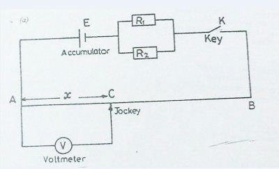
You are provided with a voltmeter V, a chemical cell/battery E; two standard resistors R1and R2; a potentiometer AB; a key K; a jockey and other necessary materials.
(i) Set up a circuit as shown in the diagram above.
(ii) Close the key K.
(iii) Make contact with the potentiometer wire AB using the jockey at a point C such that AC = x = 20 crn.
(iv) Read and record the voltmeter reading, V.
(v) Evaluate x-1 and V-1.
(vi) Repeat the procedure for other values of x = 30, 40,50,60 and 80 cm.
(vii) Tabulate your readings.
(viiiPlot a graph with V-1 on the vertical axis and x-1on the horizontal axis, starting both axes from the origin (0, 0).
(ix) Determine the:
(A) slope, s, of the graph;
(B) intercept, e, on the vertical axis.
(x) State two precautions taken to ensure 'accurate results.
(b)(i) State two devices in which Ohm's law does not apply.
(ii) A current of l A is supplied to two resistors of resistances 2Ω and 3 Ω connected in parallel. Calculate the current in each resistor.
Observation: You are provided with a voltmeter V, a chemical cell/battery E; two standard resistors R1and R2; a potentiometer AB; a key K; a jockey and other necessary materials.
(i) Set up a circuit as shown in the diagram above.
(ii) Close the key K.
(iii) Make contact with the potentiometer wire AB using the jockey at a point C such that AC = x = 20 crn. (iv)Read and record the voltmeter reading, V.
(v)Evaluate x-1and V-1.
(vi)Repeat the procedure for other values of x = 30, 40,50,60 and 80 cm.
(vii)Tabulate your readings.
(viii Plot a graph with V-1on the vertical axis and x-1on the horizontal axis, starting both axes from the origin (0, 0).
(ix) Determine the:
(A) slope, s, of the graph;
(B) intercept, e, on the vertical axis.
(x) State two precautions taken to ensure 'accurate results.
(b)(i) State two devices in which Ohm's law does not apply.
(ii)A current of l A is supplied to two resistors of resistances 2Ω and 3 Ω connected in parallel. Calculate the current in each resistor.
This question was popular among the candidates and they gave good accounts of themselves. Some of them could not evaluate the required reciprocals of V and X and those that did, could not express the results to required number of decimal places. Determination of the intercept C on the vertical axis was a problem because of poor scale used by most candidates.
The part b (i) and (ii) were poorly attempted.
The expected answers are:
Observations
(i) Six values of x read and recorded in cm to at least 1 decimal place
(ii) Six values of V read and recorded in volts to at least 1 decimal place and in trend, Yz mark each.
[Trend: V increases as x increases]
(iii)Six values of X-1 correctly evaluated to at least 3 decimal places.
(iv) Six values of V-1 correctly evaluated to at least 3 decimal places
(v) Composite table showing x, V, X-1 and V-1.
GRAPH [06]
(i) Axes correctly distinguished 1/2 mark each.
(ii)Reasonable scales,1/2 mark each.
(iii)Six points correctly plotted,1/2mark each.
(iv) Line of best fit
Note: If origin not shown, deduct 1/2 mark for d.i.
SLOPE [02l
(i)Large right angled triangJe
(ii) ∆V-1 correctly determined
(iii)∆x -1 correctly determined
(iv) (∆v-1)/(∆x-1) correctly evaluated
INTERCEPT [01]
Intercept on the vertical axis:
correctly shown
correctly recorded
ACCURACY [01]
Based on teacher's value of resistance per unit length ofpotentiometre wire slope = s = resistance per unit length ± 10%
PRECAUTIONS [02]
Award 1 mark each for any two correct precautions
e.g
Tight connections/clean terminals was ensured
Key removed when reading are not being taken
Parallax error avoided in reading voltmeter/rule
Zero error noted and corrected for in the voltmeter/rule
Dragging jockey along wire avoided
(Accept any other valid precautions).
(b)(i) Award 1 mark each for any two correct devices stated:
e.g. - Diode (p-n)
- Valves
- Transistors, metal rectifier
(Accept any other correct devices)
(ii) 1/R= 1/R1 + 1/R2
= ½ + 1/3 = 5/6
R = 6/5 Ω
V = IR = 1 x 6/5 = 6/5 V
I2Ω = 6/5 ÷ 2 = 3/5 A
I3Ω = 6/5 ÷ 3 = 2/5 A
Alt. Method
I1 = 2/5 × 1 =0.4 A
I2= 3/5 ×1= 0.6A
Alternative B
Question 4
(a) Diagram
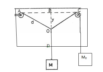
Using the above diagram as a guide, carry out the following instructions.
(i) Attach the mass Mo to one end of the thread provided. Fix the other end of the thread to pulley a on the force board. Pass the thread through pulley C.
(ii) Hang the force board vertically. Fix a drawing paper on the board behind the thread.
(iii)Draw a line on the paper along the direction of AC. Locate and mark the mid point B of line AC.
(iv)Draw a normal to AC at B.
(v)By means ofa loop of thread, suspend mass M = 70 g from AC. Adjust the position of the loop so that the line of action of the weight of M lies along BP, the normal to A C.
(vi)Ensure that M and Mo hand off the force board. Trace the paths AO, OC and OP of the thread.
(vii) Measure and record y = BO. Also measure and record d = AO.
(viii) Evaluate 1 = y /d
(ix)Repeat the procedure for other values of M = 100, 120, 150 and 170g.
(x) Tabulate your readings.
(xi)Plot a graph with I on the vertical axis and M on the horizontal axis.
(xii) Determine the slope, s, of the graph.
(xiii)State two precautions taken to ensure accurate results.
(attach your traces to your answer booklet.)
(b )(i) State parallelogram law of vector addition.
(ii) State the conditions necessary for a body to be in equilibrium when acted upon by a number
of parallel coplanar forces
Observation: This question was well attempted by many candidates.
Second observations
(i) Five complete drawings showing AO and AC at right angles to BP.
(ii) Five values ofy = BO correctly measured and recorded in em to at 1 decimal place and in trend, (Trend: yincreases as M increase)
(iii) Five values of d = AO measured and recorded in em to at least 1 decimal place and in trend. (Trend; d increases as M increase)
(iv) Five values of L = y/d correctly evaluated and recorded to at least 2 decimal places.
(vii) Composite and complete table showing M, y, d and L
Note: If no traces attached, award zero for (i) - (iii)
GRAPH (05)
(i) Axes correctly distinguished 1/2 mark each
(ii) Reasonable scales, ':1/2 mark each
(iii) Five points correctly plotted
(iv) Line of best fit
SLOPE (02)'
(i) Large right angled triangle
(ii)∆L correctly read and recorded
(iii)∆M correctly read and recorded
(iv) ∆L/∆Mcorrect1y evaluated
ACCURACY [Oll
Based on slope = 1/(2M0) to within ± 10% of supervisor's value of M,
PRECAUTIONS [02]
Award 1 mark each for any two correct precautions e.g
Force board firmly fixed.
Parallax error avoided in reading metre rule
Ensured M and M0were at rest before taking readings
Zero error was noted and corrected on the metre rule
Ensured AC was horizontal
Neat drawings
(Accept any other valid precaution).
(b) (i) The parallelogram law of vector addition states that if two vectors are represented in both magnitude and direction by the adjacent sides of a parallelogram, the resultant of the vectors is represented in magnitude and direction by the diagonal of the parallelogram drawn from the common point.
(ii)For a body to be in equilibrium under the action of parallel Coplanar forces the sum of the forces in one direction (sum of upward forces) must be equal to the sum of the forces in the opposite direction (sum of downward forces). the algebraic sum of the moments about any point is equal to zero. (OR the sum of clockwise movements about any point is equal to the sum of anti clockwise movements about the same points].
Alternative B
Question 5
(a) Diagram
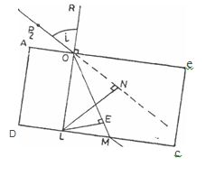
You are provided with a rectangular glass prism, drawing board, drawing papers, four optical pins
and other necessary apparatus.
Using the diagram above as a guide, carry out the following instructions.
(i) Trace the outline ABCD of the glass block on a sheet of paper attached to the drawing board.
(ii)Remove the block and mark a position 0 such that AO is about one quarter of AB.
(iii) Draw the normal ROL and the incident ray such that I = 20°.
(iv)Fix two pins at points PI and P2 on the incident ray.
(v) Replace the block and fix two other pins at points P3 and P4 such that the pins appear to
be in a straight line with the images ofthe pins appear to be in a straight line with the
images of the pins at PI and P2 when viewed through the block from the side DC of the
block.
(vi) Remove the block and join the points P 4 and P3 producing the line to meet DC at M.
(vii) Draw' a line to join points 0 and M.
(viii) Draw the normals LE and LN to the refracted ray and the extended incident ray
respectivel y .
(ix) Measure and record the lengths LE and LN.
(x)Repeat the procedure for other values of! == 3°, 40°,50° and 60°.
(xi)Tabulate your readings.
(xii) Plot a graph with LE on the vertical axis and LN on the horizontal axis.
(xiii) Determine the slope, s, of the graph.
(xiv) Evaluate K = 1 /s
(xv) State two precautions taken to obtain accurate results.
(Attach your traces to your answer booklet.)
(b)(i) What is meant by the statement: the refractive index of glass is 1.5?
(ii) The bottom of a pool 4m deep, appears to be displaced by 1m when viewed from above.
Calculated the refractive index of water in the pool.
Observation: Well attempted by most candidates. However, some candidates failed to actually perform the experiment as evident in the traces they submitted which bears no pin holes. Some responding candidates could not draw LE and LM accurately.
Evaluation of Cos (θ)/2 was a challenge to some of the candidates. Rather they were evaluating Cos θ/2.
The part (b )(i) and (ii) was poorly answered.
The expected answers are:
Second observations
(a) (i) Five complete traces showing at least, incident, refracted and emergent rays: LE, LN.
(ii)Five values of i recorded in degrees
(iii)Five values of LE measured and recorded in cm to at least 1 decimal place, and in trend.
(Trend: As I increases LE increase).
(iv) Five values ofLN measured and recorded in em to at least 1 decimal place and in trend.
(v) Composite table showing at least i, LE and LN
NOTE: I. Award zero for (i), (ii), (iii) and (iv) if traces is not attached or
II. If no pin marks are observed on attached traces award zero for (i) - (iv).
GRAPH (06)
(i) Both axes correctly distinguished,
(ii) Reasonable scales, Y:z mark each.
(iii)Five points correctly plotted
(iv) Line of best fit
SLOPE [02]
(i) Large right angled triangle
(ii)∆LE correctly determined
(iii)∆LN correctly determined
(iv)∆LE correctly evaluated
∆LN
EVALUATION [011
Correctly substituted for k = l/s
correct arithmetic
ACCURACY [OlJ
Based on teachers refractive index of glass = 1.5 + 5%.
K = refractive index
PRECAUTIONS [02]
Award 1 mark each for any two correct precautions
e.g.
- Pins are located vertically
- Pins are adequately spaced (at least 4 em).
- Avoided parallax error while reading the protractor/ruler
- Repeated readings (shown on table and traces)
- Neat traces
Zero error noted and corrected for on metre rule
(Accept any other valid precautions)
(b) (i) Refractive index means that the speed of light is 1.5 times greater in air than in the glass
(Accept any other valid explanation)
(ii) Real depth = 4m
Apparent depth = 4 - I = 3m
n = Real depth
Apparent depth
= 4/3
= 1.33
Alternative B
Question 6
(a) Diagram
You are provided with two standard resistors Rand S, a voltmeter, an accumulator, a rheostat and
other necessary apparatus.
(i)Set up a circuit as illustrated in the diagram above.
(ii) Connect the voltmeter across R.
(iii)Close the key K and vary the rheostat to set the voltmeter reading VI across R to 0.3 V.
(iv)Open the key and disconnect the voltmeter.
(v) Now connect the voltmeter across S and close the key.
(vi)Read and record the voltmeter reading V2•
(vii) Repeat the procedure for other values of VI = 0.6,0.9, 1.2 and 1.5 V by varying the
rheostat. In each case, read and record the corresponding value ofV2.
(viii) Tabulate your readings.
(ix)Plot a graph with VI on the vertical axis and V2 on the horizontal axis.
(x)Determine the slope s, of the graph.
(xi) What is the physical significance of the slope?
(xii)State tHe precautions taken to obtain accurate results.
(b) (i)State two reasons why the key in the circuit should be opened when readings
are not being taken.
(ii)Explain why a battery of eight dry Leclanche cells each of emf 1.5 V is not used in
place olu car battery of 12 V to start a car engine.
Observation: This was the most popular question and well attempted by majority of the candidates. Majority of the respondent candidates were unable to explain the physical significance of the slope. The part (b) was poorly attempted. Many candidates only state that the battery will not run down but they are not conversant with the fact that the ohmic resistance of the circuit will increase which will in turn increase the temperature of the circuit.
3(a)observations
(i)Five values of VI read and recorded in volts to at least 1 decimal place.
(ii) Five values of V, read and recorded in volts to at least 1 decimal place and in trend.
[Trend: As V I increases, V 2 increases]
(iii)Composite table showing VI, and V2
GRAPH [06J
(i) Axes correctly distinguished, 12 mark each
(ii)Reasonable scales, 12 mark each
(iii)Five points correctly plotted
(iv)Line of best fit
SLOPE [02]
(i)Large right angled triangle
(ii)∆VI correctly determined
(iii)∆V 2 correctly determined
(iv) ∆VI/∆V2correctly evaluated
ACCURACY [01]
Based on teachers values of Rand S
Slope = R/S ± 10%
DEDUCtION [01]
The physcial significance of the slope is the ratio S to R or R/S
PRECAUTIONS [02]
Award 1 mark each for any two correct precautions
e.g
Tight connections/clean terminals was ensured
Key removed when readings were not being taken
Parallax error avoided in reading voltmeter
zero error noted and corrected for in the voltmeter
(Accept any other valid precautions).
(b )(i) The key in the circuit should be opened so as not to drain the battery/cell.
so as not to increase the ohmic resistance/temperature of the circuit
(ii) The current produced by the dry Lec1anche cells is too low compared to the current produced by an accumulator due to the high internal resistance of the Leclanche-cell (or due to the low internal resistance of the accumulator).